The CTPCI extension comes with 2 cards: one that is plugged on the CT60/CT63 and that is connected to standard IDE ribbon cables to the second card, which holds 4 PCI slots. Here I describe the different steps to install it, and stuff to take care off.
0. Update everything
Before thinking of using the CTPCI, be sure your CT60 is flashed with the latest version of the firmware for the different chips (ABE and SDR), and the TOS with CTPCI support.
1. Preparing the second card (the one with the 4 PCI slots).
You need a standard molex alimentation from your ATX PSU (Power supply unit), along with an extra orange wire you must take from one of the cables of your PSU. The orange wire is used to bring 3.3V to the board. I took one from a SATA connector of my PSU, as I do not have any SATA device to plug on the Falcon. Press the lever of the small orange block to open it, enter the wire in the hole, release.
See http://en.wikipedia.org/wiki/Serial_ATA#Power_supply and http://en.wikipedia.org/wiki/ATX_Power_Connector#Power_supply to check if your ATX PSU provides you some wire with 3.3V .
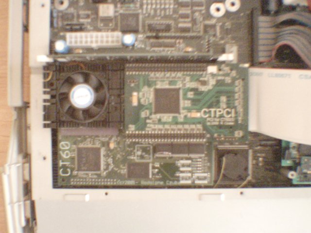
2. Preparing the first card (the one to be plugged on CT6X).
Plug the 2 IDE ribbons cables to PCI1/J11 and PCI2/J12 connectors. Note: Mark down which is PCI1/J11 and PCI2/J12. Once plugged on the CT60, you won't be able to see which is where, because the writing on the PCB are below. There is a third one if you want to use the IDE port of this board.
3. Preparing the motherboard and CT60.
To plug the CTPCI board on the CT60, the easier is to unplug the CT60 from the motherboard. Between the SDRAM, and the fan+cooler, there is very little space remaining, so unplugging the CT60 is the safest way to properly put it.
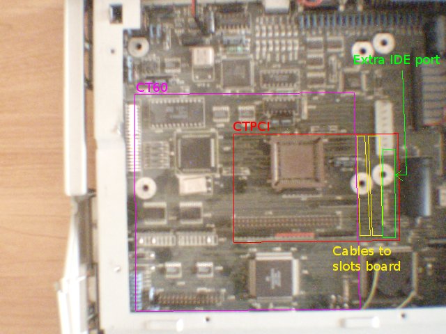
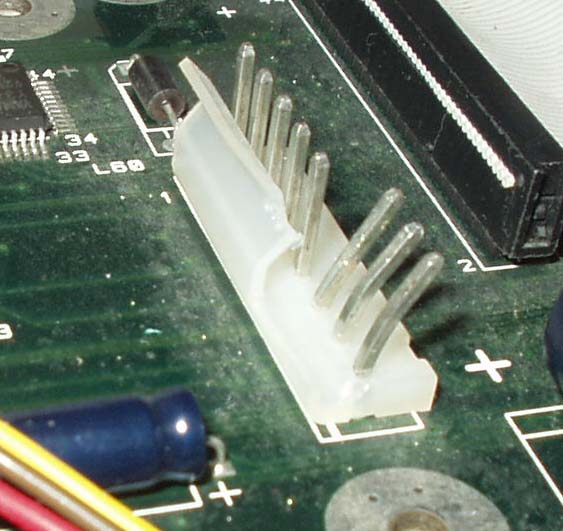
There is a little work to do on the motherboard: The original power connector of the motherboard goes straight to the IDE connectors of the CTPCI board. You'll have to cut the plastic part (at least to the 4th pin), and bend the 3 lowest pins. The pins are big enough to not break when you bend them, and you can put them back in original position, if you need to restore everything.
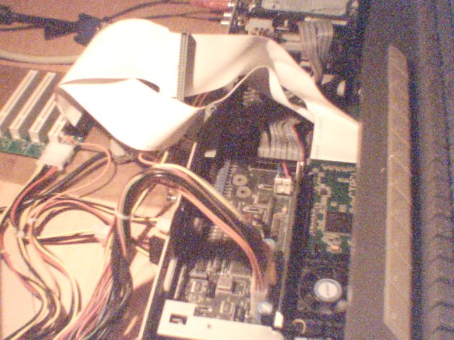
When this is done, you can plug back the CT60 on the motherboard. If you removed the shielding (that is not my case), you can place the ribbons below the ct60, and outputting them to the left of the motherboard.
Be careful if you use the original Atari keyboard, as it will touch the expansion port at the top of the CTPCI card. Protect the expansion port (and/or the keyboard PCB) to avoid any possibility of short circuit there.
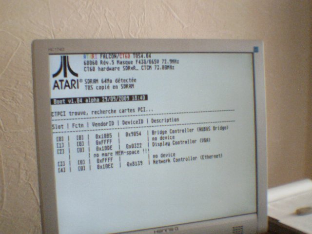
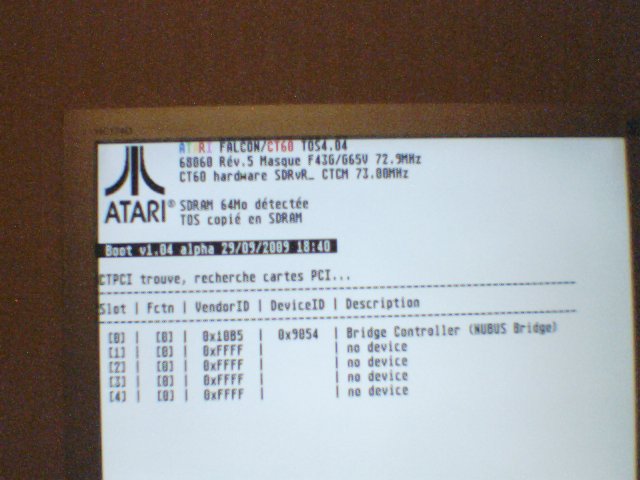
4. Testing
You can connect the 2 IDE ribbons cables to J5 (from PCI1/J11) and J6 (from PCI2/J12) of the second card (with slots). Double check the daughter board receives power. Check again everything is properly plugged. My Falcon did not boot up the first time I powered it up. If this happens, press RESET button of the motherboard several times.
Consider reducing the clock frequency of the CPU if any of these happens, specially if like me you do not have a Revision 6 CPU:
- 'Warning: BAD ROM CRC IN CHIP E' when booting TOS (only happens at power up though, is not displayed after reset)
- Falcon resets after a few seconds
- Graphical corruptions in demos (like for example Starstruck from TBL)
5. Plugging PCI cards
You can finally plug the PCI cards on it. For the PCI cards, the back planes must be on the same side as the power connector of the slot card. Currently, here are the PCI cards I have at hand:
- 0x10de:0x0322 Geforce FX 5200 (3.3V and 5V card)
- 0x10ec:0x8139 Network card #1 (3.3V and 5V card)
- 0x1274:0x1371 Soundblaster 128 PCI (5V card, not usable on CTPCI)
- 0x121a:0x0002 3DFX Voodoo 2 (5V card, not usable on CTPCI)
- 0x10ec:0x8139 Network card #2 (5V, not usable on CTPCI)
- Card with 4 USB ports (5V card, not usable on CTPCI). Damn I bought it for CTPCI :-(.